


What is Plain Milling? Complete Guide for Beginners
Plain Milling is a fundamental machining technique. This is very important for removing large amounts of material efficiently from flat surfaces. You use these parts in heavy equipment, structural components, and general manufacturing industries.
In this article, you will read its definition, types, advantages, limitations, and important applications.
Contents
What is Plain Milling?
Definition and Basic Concept
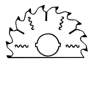
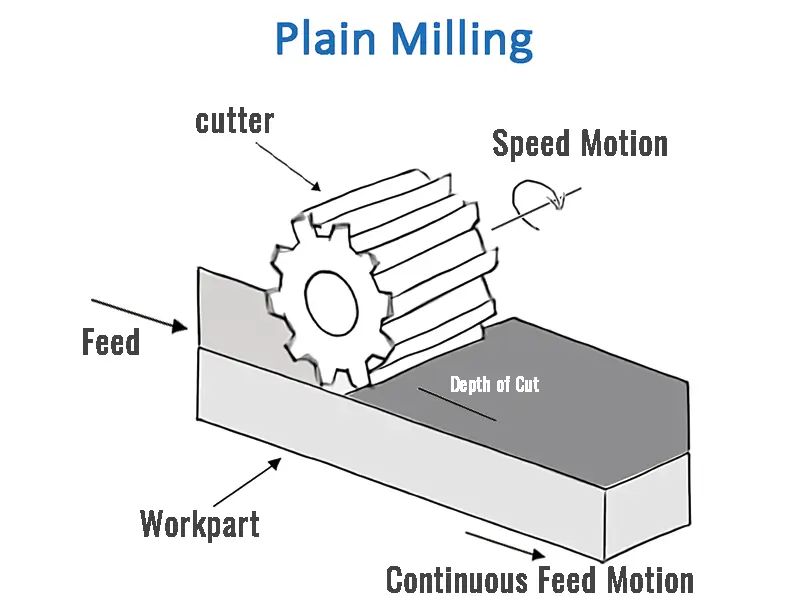
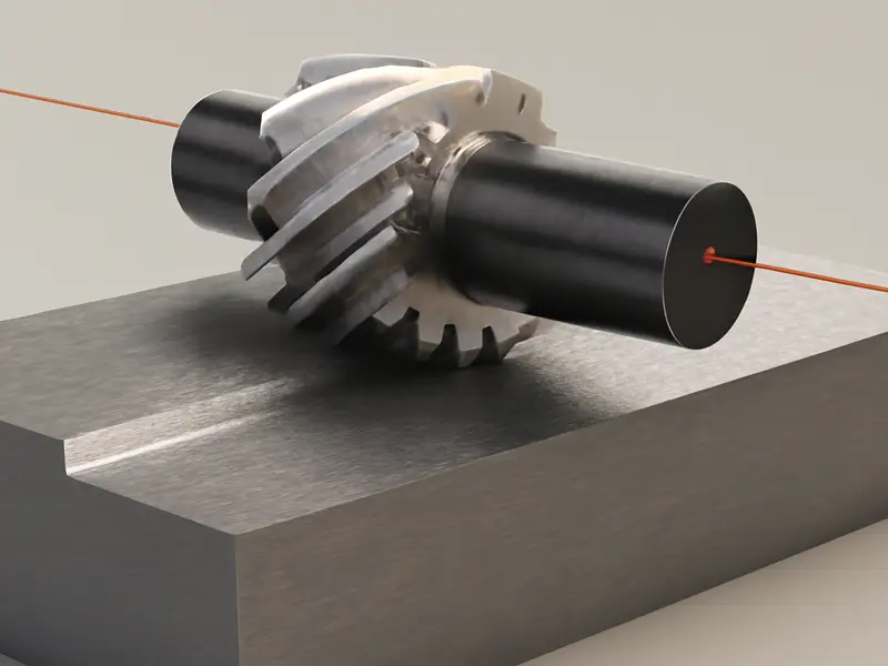
Plain or slab milling uses a cylindrical cutting tool with multiple edges on its periphery to generate a flat surface parallel to the cutter axis. It is commonly performed on a horizontal milling machine, but the surface orientation alone does not define the process.
CNC machining companies and other machine shops can use a plain mill to remove stock with its peripheral edges. Cutting conditions must match the tool, machine, and work material.
How Plain Milling Works
The cutting tool is typically supported on an arbor. Relative feed carries the workpiece past the rotating cutter, usually perpendicular to the cutter axis; the tool does not move perpendicular to its own cutting feed.
- The final surface finish
- The width of the cut
- Subsequently, the depth of the cut
- The rigidity of the setup
- And the properties of the material.
Then, you should look at the importance of your tool selection, the precise feed rate, the speed of the rotation, and your use of cooling fluids. You must fine-tune all these.
Plain Milling and Related Milling Operations
Plain Slab Milling
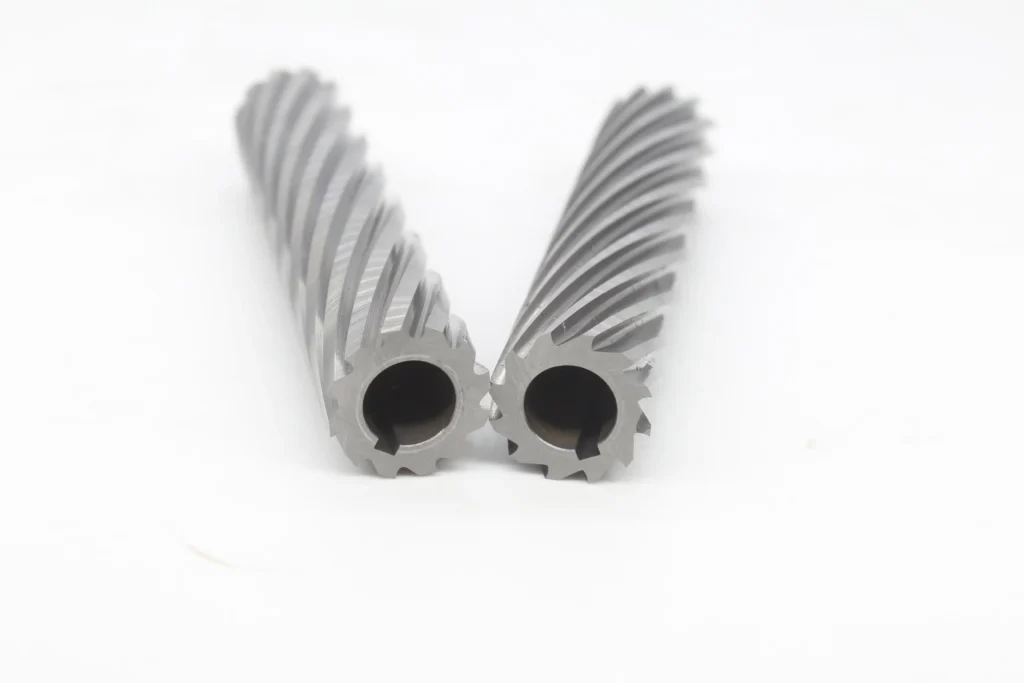
Plain slab milling uses peripheral teeth on a cylindrical cutter to produce a flat surface. The cutter width along its axis and the selected passes determine surface coverage; cutter diameter is not the dimension that defines that width.
Side Milling
Then, you should look at side milling. It uses specialized side milling cutters with teeth mainly on the sides and periphery. This is good for machining vertical flat surfaces or for sizing the width of a part. Configurations include the staggered tooth, plain, and half side milling cutters.
Face Milling
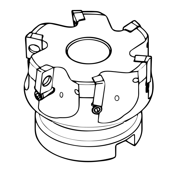
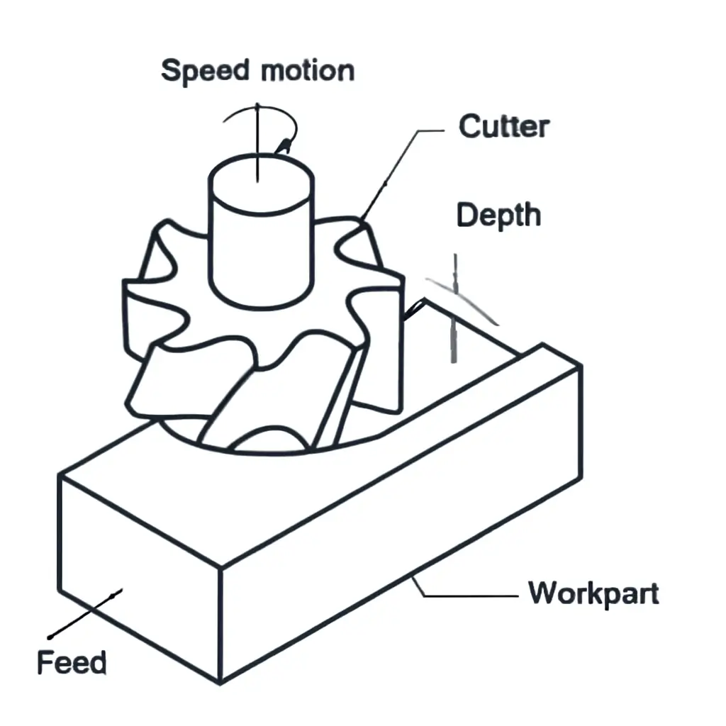
In face milling, the cutter axis is approximately perpendicular to the machined plane. Peripheral and face cutting edges contribute according to cutter geometry. It is a related operation, not a subtype of plain milling, and its productivity cannot be ranked below slab milling without application data.
End Milling
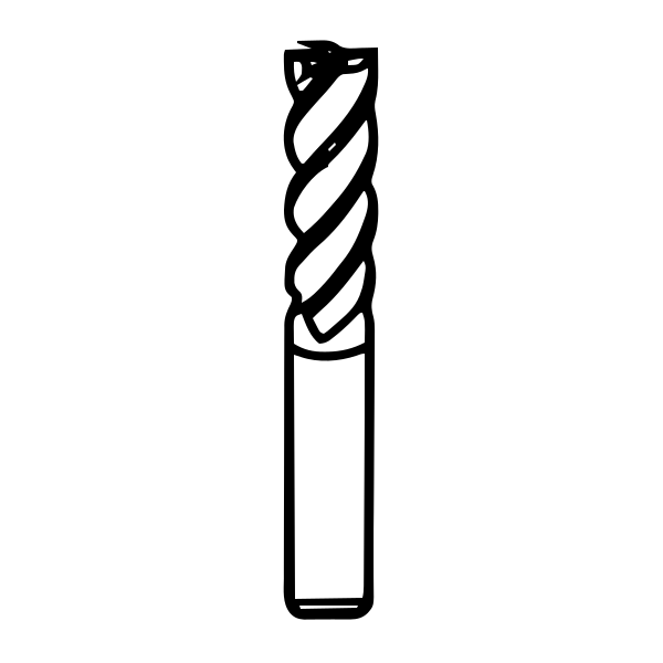
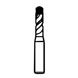
End milling uses end mills to machine features such as pockets, slots, shoulders, and smaller surfaces. It is a related milling method, not a compulsory finishing step after every slab-milling pass.
Gang Milling
Finally, make sure to consider gang milling. This involves mounting multiple cutters like plain mills on a single arbor. The purpose is to perform multiple operations simultaneously. This provides high productivity for parts requiring multiple flat and vertical surfaces. The payoff is high, but the price is a rigid setup due to aggressive cutting forces.
Plain Milling Toolpath Methods
The path you choose for your tool is just as important as the tool itself.
Up Milling
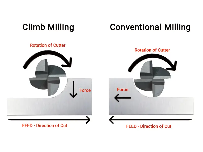
Up milling is also called conventional milling. In peripheral milling, tooth motion at contact opposes the workpiece feed; chip thickness grows from near zero. This does not remove mechanical backlash, although it can avoid the pull-in tendency of climb milling on unsuitable feed systems. Rubbing at entry can affect finish.
Down Milling
In peripheral down or climb milling, tooth motion at contact follows the workpiece feed, and chip thickness decreases toward zero. It can improve finish in suitable conditions, but the machine feed system and workholding must resist pull-in and control backlash.
Linear Straight Pass
A straight pass is a common path for slab milling. Material-removal rate depends on feed, width, depth, and available machine capacity; a straight path alone does not guarantee a higher rate.
Advantages of Plain Milling
High Material Removal Rate MRR
Plain milling can remove substantial stock with a suitable cutter and rigid arbor support. Permissible chip load depends on the tool, material, engagement, and machine capacity.
Versatile for Large, Flat Surfaces
Plain milling can produce large, flat surfaces in suitable metals and plastics. Tool material, geometry, and cutting data must match the workpiece; not every setup is suitable for the hardest steels.
Efficient Production
Plain milling can be productive for repeated flat-surface operations. Compare its cycle time with shaping or planing for the actual job, and monitor the process rather than assuming that the initial settings never need adjustment.
Excellent Surface Finish Capability With Climb Milling
Climb milling can support a good finish when the cutter, feed system, workholding, and cutting conditions are suitable. Required finish and dimensional accuracy still need verification.
Applications of Plain Milling
Basic Block and Plate Preparation
First, the most common application is squaring and sizing raw material for further machining. You would rather use a plain mill for this initial roughing cut. However, it depends on the required width.
Machine Tool Parts
Then, you should look at the machining of bases, columns, and beds for machine tools, fixture plates, and jigs. These flat surfaces are essential for securing parts and tools.
Heavy Equipment and Rail
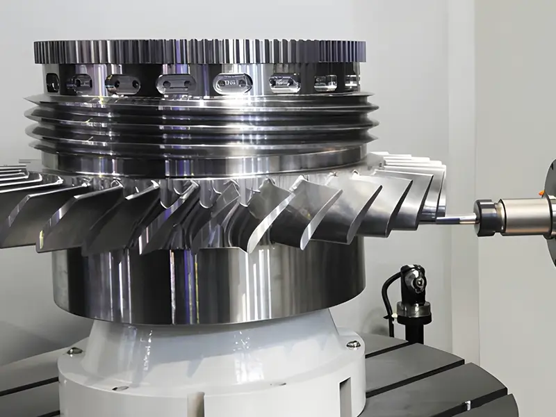
After that, the automotive factories use it for milling engine block faces and machining flat surfaces on large castings. Aerospace companies need it for material removal on structural frames and large assemblies.
Structural Manufacturing
Moreover, manufacturers use it for preparing joints and fitting surfaces in heavy fabrication. The precision is very important here, as failure is not an option.
Die and Mold Bases
Plain milling is one option in mold and die making. It can prepare accessible flat base and plate surfaces; inspect their flatness, dimensions, and other drawing requirements. Sounding hollow is not a machining acceptance criterion.
Conclusion
Plain milling uses peripheral cutter edges to make flat surfaces parallel to the cutter axis. Choose the tool, support, feed direction, and cutting conditions for the application, then inspect the result against the drawing; it is not automatically superior to other milling methods.