



Peck drilling: why a drill chips on re-entry
If a drill survives the first penetration but chips during a later peck, check what happens between cuts before changing the cutting data. Retained chips and the point where rapid approach changes to feed deserve separate checks. First establish whether the damage actually begins on re-entry: a chipped drill inspected after the hole is finished cannot identify the damaging movement by itself.
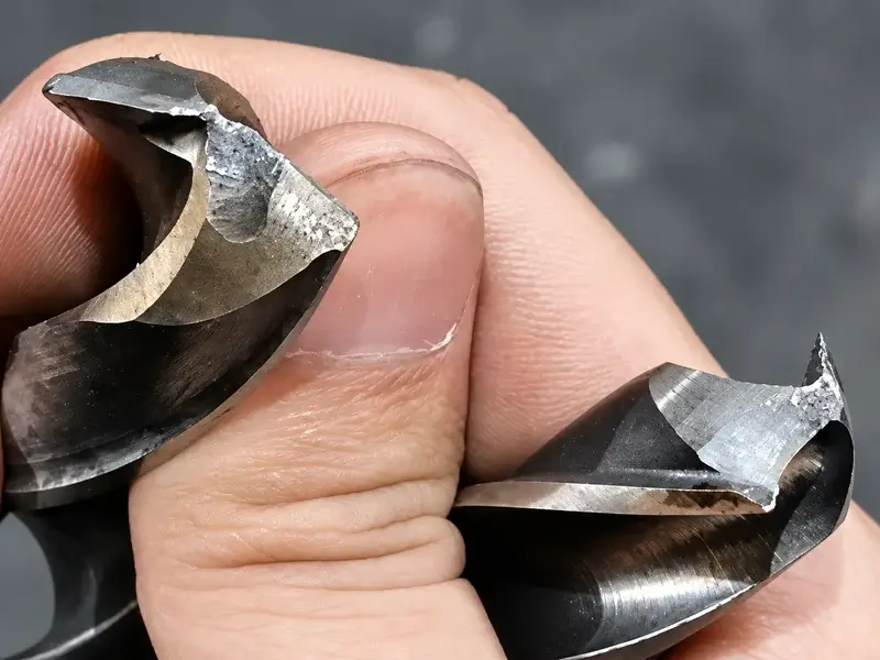
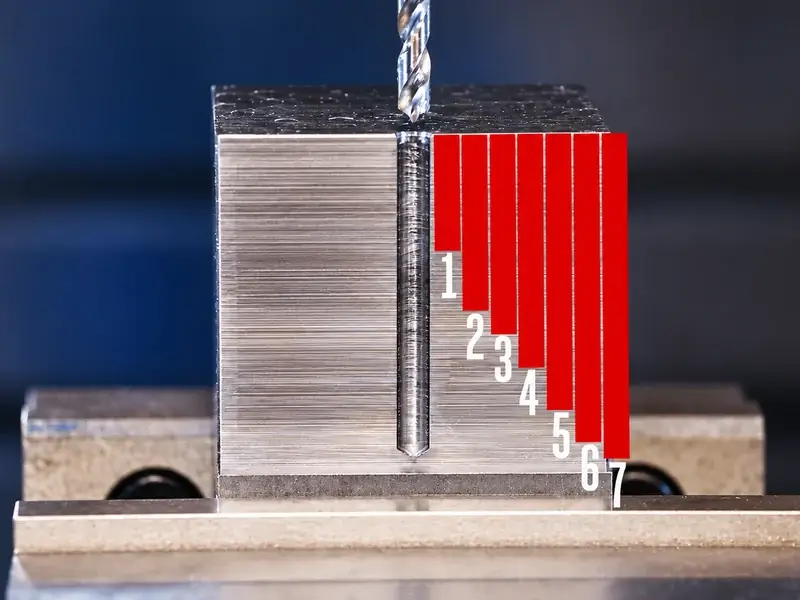
Peck drilling divides a hole into successive cutting passes, with intervening motion intended to break chips or help remove them. That added motion can help chip evacuation, but its name does not prove that chips have cleared or that the return path suits the drill. The useful question is what the tool encounters as it withdraws, returns and resumes cutting.
Locate the event before blaming the return
Preserve the drill, chips and hole evidence after a failure. Follow the machine's stopped-machine and isolation procedures before inspection or chip removal. Record whether the first sign of trouble occurred during the established cut, withdrawal, travel back into the hole, or renewed cutting beyond the previous peck endpoint.
Use existing observations and any available cycle or load record to support that timing. A load change can help locate an event, but does not identify its cause alone. If the only evidence is a damaged outer corner after the complete cycle, keep the phase marked as unknown. Do not rerun a damaged setup simply to discover the instant of failure.
This distinction changes the investigation. Chips packed in a flute support a chip-path concern. Damage during withdrawal requires a look at binding or contact on the way out. Damage associated with the return calls for a review of retained material and approach motion. If damage develops during continuous cutting instead, use the broader drill-breakage diagnosis; a re-entry adjustment may address the wrong part of the process.
Compare the suspect setup with the last stable one, including drill condition, holder/runout, workholding, coolant delivery and offsets. The same program and nominal cutting data on two machines do not establish identical physical conditions or identical cycle execution.
If the drill has an exchangeable head, also separate progressive wear from sudden head chipping and preserve the head-body interface evidence. That construction-specific check does not identify which peck movement caused the damage.
Separate the four functions inside a peck drilling cycle
A shorter peck, a larger retract and an earlier change to feed are not interchangeable corrections. Read the cycle as distinct functions before deciding which one needs attention.
| Cycle function | What it controls or is intended to do | What to verify for this failure |
|---|---|---|
| Peck increment | How much further the drill cuts in a pass | Does the selected increment suit the actual drill, material and chip formation? Reducing it does not, by itself, establish a safer return path. |
| Short chip-breaking retract | Interrupts cutting with a limited withdrawal | Does this motion merely break the chip, or does the process also provide a way for the fragments to leave? A short retreat is not proof of evacuation. |
| Chip-clearing return position | Provides a withdrawal position for chip removal and coolant access | Where does the tool actually travel relative to the part and fixtures, and do chips leave the flute and hole? Do not assume the R plane is the workpiece surface. |
| Re-approach and feed changeover | Determines the return motion before cutting resumes | Where does rapid motion end relative to the previous peck endpoint, and what material may remain in that path? Verify the installed control's definition rather than copying a clearance value. |
The previous peck endpoint is a programmed tool position. It is not a measurement of the height of retained chips. Chips may remain in the hole or on the flutes after a withdrawal, so nominally returning to an already-drilled position does not prove that the drill will encounter empty space.
If rapid approach reaches retained material, abrupt contact is a plausible damage mechanism to investigate. Starting feed earlier may change that contact, but it neither removes the obstruction nor proves that the chip path is adequate. A motion review and an evacuation check must therefore remain separate.
Inspect chip form and flute loading together with the actual coolant route. Coolant visible around the part is not evidence that it reaches the cutting zone or carries chips out of the hole. Clear a confirmed restriction using the approved stopped-machine procedure; do not use the returning drill to test whether a suspected chip pile is still there.
G73 and G83 are starting points for reading the manual
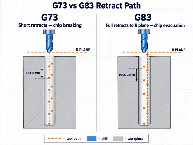
On a milling machine, the G73 drilling cycle is often associated with short chip-breaking retracts, while the G83 drilling cycle is associated with larger chip-clearing withdrawals. The installed controller, software, machine-builder configuration and selected cycle mode determine the actual sequence.
Haas milling documentation illustrates why the mode matters. Its G73 page describes a mode that returns to the R plane after a group of passes, as well as a mode that returns there after the pecks are complete. Its G83 page distinguishes the R-plane position above the part from additional chip-clearing travel. A simple rule that G73 can never return to R between cutting passes would therefore misdescribe even that manufacturer's documented options.
Use the exact manual for the machine being investigated to identify the peck increment, retract behavior, return position and rapid-to-feed changeover. Check their reference positions and units. A setting name, parameter number or value from another control is not a portable definition. If the meaning is unclear, ask the machine builder or qualified service support to resolve it before any change.
Also confirm that pecking is appropriate for the drill. Harvey Performance's peck-cycle guidance varies by drill and work material; OSG describes coolant-fed ADO carbide drills designed for drilling without pecking. These are tool-specific approaches, not competing universal rules. Drill design, usable length, hole geometry and coolant capability must support the chosen strategy. Neither always pecking carbide nor never pecking carbide is a sound substitute for that check.
Turn the evidence into a controlled verification
Give the programmer or machine support team a motion-review record, not just a request for more clearance. Include:
The machine, controller and software identification, the exact cycle block and relevant modal state, offsets and as-found configuration.
The drill identity and condition, work material, hole geometry, holder/runout findings and coolant arrangement.
The suspected damage phase, what supports that timing, and photographs or inspection notes showing retained chips, flute loading and edge damage.
A description of each internal movement, including the return position and the documented rapid-to-feed transition, with unresolved points clearly marked.
Establish tool, part and fixture clearances before a live cutting verification. Qualified personnel should review the intended path in the available no-cut graphics or simulation and follow the machine builder's approved prove-out procedure. Confirm how single block treats internal canned-cycle movements and how dry-run or override functions affect that control. Do not assume one press stops every peck movement, or that a reduced override makes an uncertain path safe.
Simulation cannot prove that real chips will leave the hole, and a no-cut motion check cannot validate loaded cutting behavior. If the path, units, offsets or chip-clearing arrangement remain uncertain, keep the cycle out of production until those questions are resolved.
After the documented checks, change one authorized process variable at a time. Record the change and inspect the edge, chips and hole during the controlled verification appropriate to the process. Acceptance requires the intended motion and chip behavior as well as an acceptable tool and part. One completed hole alone does not establish the cause of the original failure or validate tool life for production.