


Stepped Hole Drilling: Which Diameter Comes First?
For the two-drill stepped-hole method described in Sandvik Coromant's technical guide, drill the larger diameter first, then the smaller. The purpose is to control how the following drill enters the prepared surface, helping its point engage centrally rather than exposing the cutting edges to an unsuitable first contact.
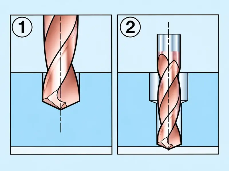
That is a definite sequence for a particular method—not a rule that every hole must be made large-first. A smaller hole followed by boring, a purpose-built multidiameter tool and a long drill entering a pilot hole are different operations. To choose correctly, identify what the next tool will touch and what will support it.
The matched two-drill method starts with the larger diameter
In the guide's two-drill route, the larger drill prepares the larger section before the smaller drill continues the hole. Tool selection must suit both diameters and depths. The entry condition of the second drill is part of that selection, not something to leave until the program is running.
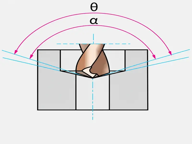
The guide gives a specific point-angle condition when the smaller tool is a CoroDrill Delta-C or Coromant Delta: its point angle should be equal to or smaller than the larger drill's. The stated aim is for the point to meet the workpiece first. “Strictly smaller” is therefore not the full documented condition, and the instruction must not be turned into an angle rule for every drill family.
Check the real point and cutting-edge form against the surface left by the first operation. A nominal point-angle label does not describe every detail of the grind or prove the resulting contact. On a section sketch, locate the second drill's initial contact and follow its engagement as it advances. If the actual tool and prepared surface do not match the documented method, resolve that mismatch rather than assuming the large-first order makes the entry safe. For an inclined entry face, consider the separate sloped-surface drilling and entry-preparation decision.
Also compare the resulting profile with the drawing. A drill-formed conical transition is not a flat shoulder. If the part requires a flat seating surface or a specified transition, the process must produce it; changing the hole order does not waive that requirement. Nor does a centered start guarantee the required relationship between the finished diameters. Their position and geometry still need measurement.
The practical decision is clear: retain large-first for a compatible two-drill route, with its entry geometry checked. If that route cannot produce the specified shoulder or engagement, choose another machining method.
Centering a point is not the same as guiding a long drill
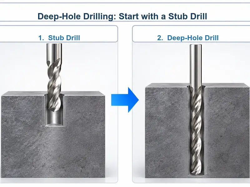
A point meeting the workpiece centrally answers an initial-contact question. A long, small-diameter drill may also need lateral support before it can run under its cutting conditions. These are not interchangeable requirements.
A shallow large-diameter opening does not automatically provide that support. Its wall is outside the smaller drill's guiding diameter. Ask where the smaller drill will actually enter a suitably matched guide bore after passing through the large opening—not merely whether there is a recess around it.
Guhring's RT100T procedure illustrates the distinction. It requires a pilot hole to guide that deep-hole drill and prohibits full-speed operation without support in the pilot. The specified pilot and entry sequence belong to that tool system; they are not universal pilot dimensions or a ready-made program for another long drill.
For your tool, establish the required pilot geometry, fit, useful guiding length and entry motion. Then decide how that pilot will be produced in relation to the larger section. If the proposed route only says “large hole first, then the long small drill,” it is incomplete until the actual support location and entry procedure are identified. A point at the bottom of a wide opening is not a substitute for the required guiding bore.
Change the route when the next cutter's job changes
If the plan is to drill a smaller hole and then bore or mill the larger section, you are no longer reversing the same two-drill method. You have selected a different cutter and a different engagement. Sandvik's guide explicitly separates drilling-and-boring from its two-drill route and starts that method with drilling, followed by boring.
For such a plan, define the prepared opening, stock to remove and the next tool's entry capability. Keep the required shoulder, depth and position relationship in view. Do not assume that a drill suited to cutting from solid can also enlarge an existing hole with its center no longer cutting; that capability must be established for the actual tool and geometry.
Pre-hole suitability is design-specific. For example, Sandvik describes its DE10 -M5F geometry as suitable for pre-drilled holes and pilot-drill applications. That is an exchangeable-tip system, not evidence that every two-insert U drill can work over any pre-hole. Neither a blanket prohibition nor an unrestricted pre-hole rule is justified by the tool's general name.
A dedicated production step drill is another route. Its diameters, axial steps and cutting edges engage according to its design; the operator is not freely exchanging two independent drilling operations. If the decision has become one of tool type or finishing allowance, use the separate step reamer versus step drill guide rather than treating all stepped tools as equivalent.
Before programming, draw the next tool in section and answer these questions:
Which surface meets the tool first? Identify the prepared cone, flat face, existing-hole edge or other actual entry surface, and the part of the cutter that contacts it.
What material will it cut? Distinguish central solid material from stock around an existing opening or along a sidewall. Check that the chosen geometry is intended for that engagement.
Where does it obtain guidance? Locate the supporting bore or other specified guidance and confirm when it becomes effective, especially for a long drill crossing a larger opening.
Make physical checks only with the machine stopped safely, and plan any trial under the site's machining and safety procedures. Record the diameters, depths, shoulder shape, tool identities and support arrangement with the proposed sequence. Verify the route on representative material, measuring the required diameters, step depths, relative position and surface finish. The accepted plan should explain both why that order was chosen and how the finished stepped hole will be checked.