



Thread Turning vs Thread Milling: Which Fits Your Setup?
For a part already held on a CNC lathe with the thread axis aligned to the spindle, thread turning is often the practical starting point. For an off-center threaded hole in a housing fixed on a machining center, thread milling is usually the more natural route, provided the machine supports the required interpolation. Choose the process that fits the workholding and machine motion before comparing cutting tools.
Both methods can produce internal and external threads. The thread specification defines the finished feature, but does not by itself select the process: check whether the part can rotate around the thread axis in the current setup, or whether a rotating cutter must travel around a stationary part. Tool access, usable thread depth and inspection requirements then determine whether that route is workable.
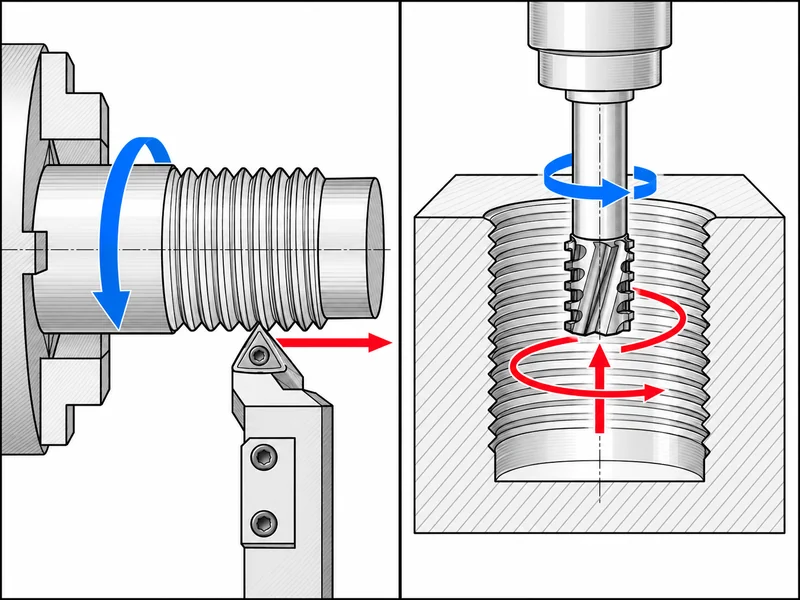
The movement tells you which process you are choosing
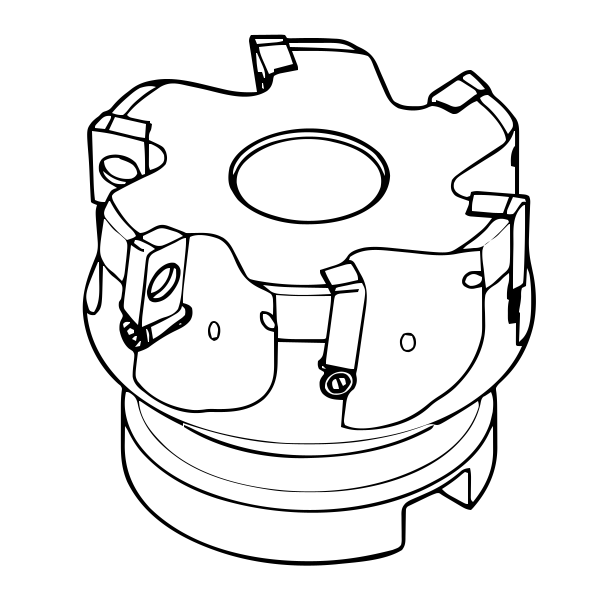
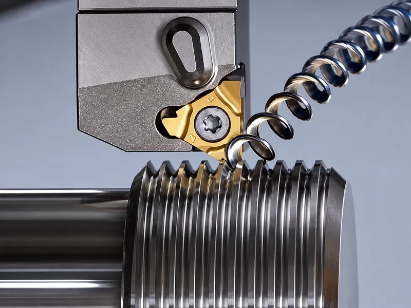
In conventional thread turning, the workpiece rotates while a threading tool advances in synchronization with the spindle. The insert does not rotate about its own axis as a milling cutter does. Its profile, position and feed relationship create the thread through the programmed passes.
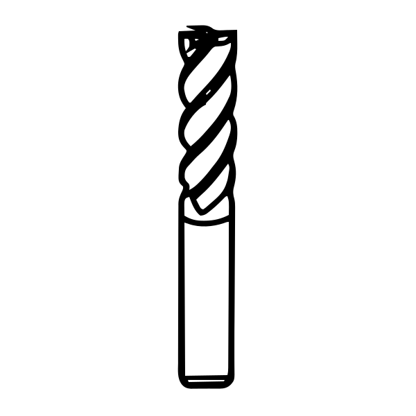
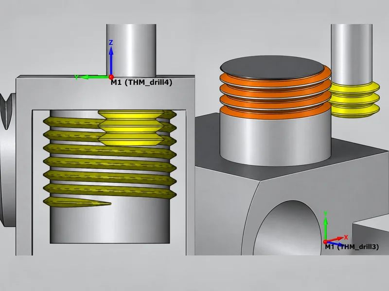
In thread milling, the cutter rotates and follows a helical path relative to the workpiece. The circular movement establishes the thread diameter while the axial movement establishes the lead. The workpiece normally remains stationary. A cutter that fits inside the bore still needs room for its cutting path, entry, exit and neck clearance.
Choosing a tool by thread size alone skips the first process decision: how will the machine generate the thread? A threading insert cannot simply replace a thread mill in the same program. Establish the required motion before comparing cutting edges.
A turn-mill machine may support both operations using different spindles, axes and tool stations. Check its actual motion and control capability rather than choosing by machine name alone. The thread-milling route needs coordinated motion that can generate the required helical path.
Keep the thread in the setup that controls the part
Consider two hypothetical jobs with the same thread specification.
A turned sleeve: the outside diameter, bore and end face are already being machined on a lathe. If the thread is concentric with the spindle and the tool can enter and leave safely, thread turning may complete the feature without moving the part to another machine. That preserves the existing datum relationship and avoids another setup.
A housing with several threaded ports: the part is fixed on a machining center, and the port axes are located from machined faces. Thread milling can keep the ports in that setup. Trying to rotate the whole housing around each port axis would introduce a different workholding problem.
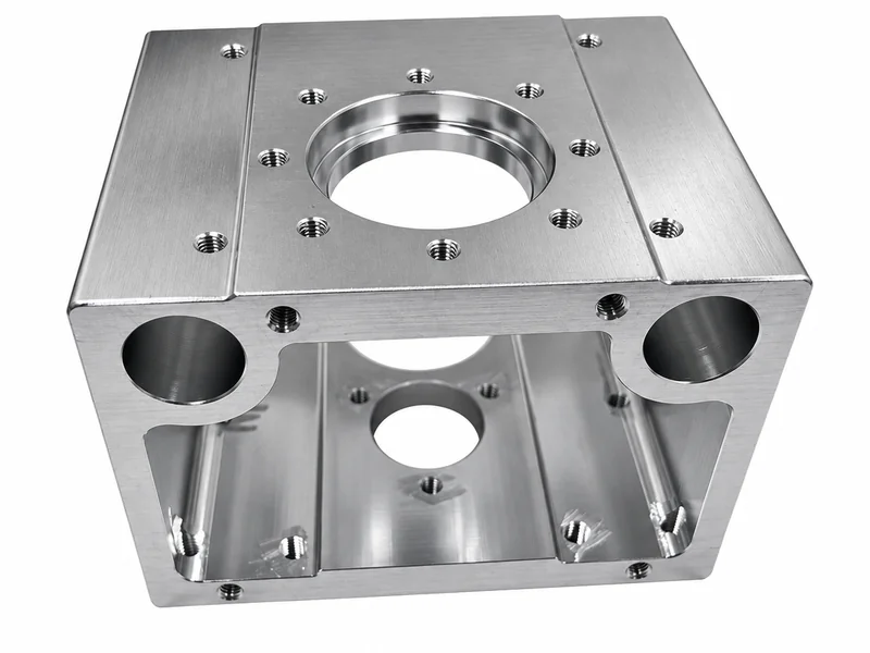
These are planning examples, not reported production trials. Their point is that nominal diameter is identical while the sensible process changes. Compare the whole route: workholding, access, tool changes, programming and inspection. A short cutting cycle can lose its advantage if it requires an extra setup.
Check access before choosing the cutting edge
Once the movement is feasible, look at the thread as a feature inside the part. “Internal thread” is not enough information. A short through thread, a blind thread close to a bottom, and a thread behind a shoulder can require different tool arrangements.
| Part condition | What to examine | How it affects the decision |
|---|---|---|
| Internal thread in a narrow or deep bore | Tool body clearance, reach and supported length | A turning bar needs space inside the bore; a thread mill needs space for both its body and its circular path. Neither is selected by thread diameter alone. |
| Thread close to a shoulder | Entry and exit path, runout space and holder clearance | The programmed path must clear the shoulder while producing the required usable thread length. |
| Blind hole | Full thread depth, drilled depth and bottom clearance | The cutter must reach the final thread without contacting the bottom. A nominal hole depth is not the same as usable thread depth. |
| Thin wall or flexible workholding | Support near the cut and evidence of movement | Cutting load and the direction of that load may matter more than the nominal speed advantage. |
| Several thread diameters | Thread form, pitch and the cutter's permitted diameter range | Some thread mills can cover multiple diameters, but compatible pitch alone does not prove that every diameter is accessible or geometrically acceptable. |
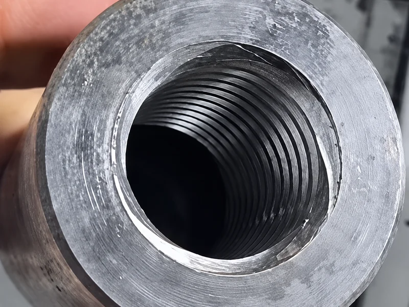
For internal threads, check the smallest opening the tool must pass through, not just the diameter where it will cut. For external threads, include the neighboring shoulder and fixture in the clearance check. A tool that looks suitable beside the drawing may still collide once the holder is included.
What must be specified before a tool can be chosen?
Prepare one complete description of the finished thread: standard and designation, diameter, pitch or threads per inch, internal or external location, handedness, usable length and tolerance class. Add the workpiece material and hardness, the drawing's inspection requirement, and the available space at the start and end of the thread.
Then add the information specific to the process:
- For thread turning: the lathe and tool station, holder or boring-bar interface, available bore clearance, thread runout or relief, and how the part is supported.
- For thread milling: the machine's interpolation capability, pre-machined bore, tool reach, neck clearance, coolant access and the intended cutter configuration.
This information lets the tool supplier check a real application instead of quoting an apparently matching cutting edge. It also gives the programmer and inspector the same definition of the job. A quotation based only on “an internal metric thread” leaves the most consequential decisions unresolved.
Make the process choice before setting the cutting data
For an internal thread, choosing a milling-capable setup still leaves tapping as an alternative. Our comparison of thread milling vs tapping looks at the prepared bore, usable blind-hole depth and cost per accepted component to help decide whether milling solves a problem that tapping does not.
Choose the route that can generate the thread in a stable, accessible setup. Confirm its usable thread length and inspection method, then select the cutting edge and develop the program. For a thread-milling route, the next calculation is the relationship between cutting-edge feed and circular toolpath feed; our thread milling feeds and speeds guide addresses that separate step.
If the setup points toward milling, review the available Sunditools carbide thread mills against the actual drawing and machine capability. Start with the motion the job needs, then choose the tool that can perform it.