


Usinage du cuivre : identification du matériau, choix PCD, refroidissement et diagnostic des défauts
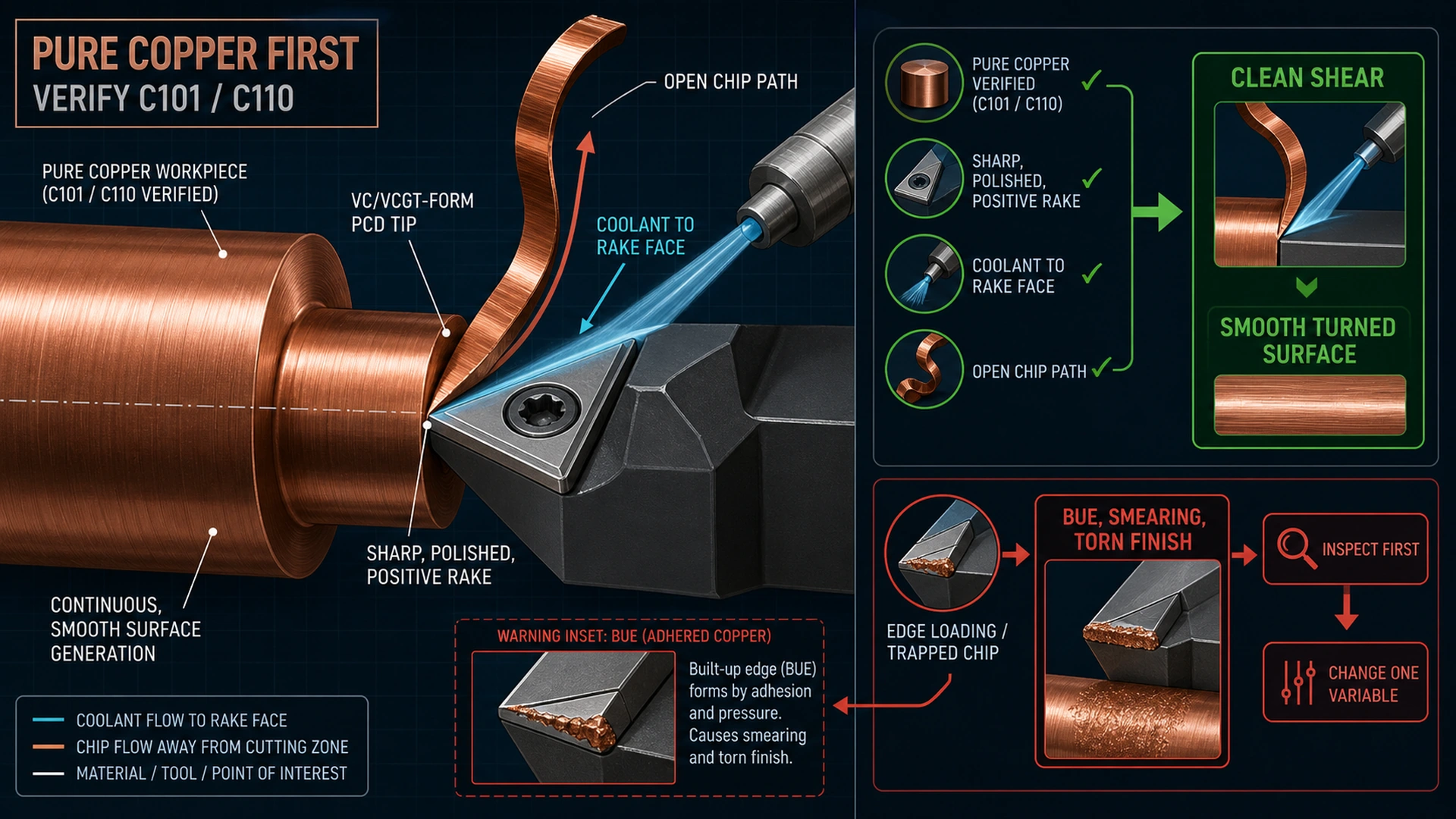
Pour usiner le cuivre, commencez par identifier le matériau : pour du C101/C110 confirmé ou un cuivre corroyé pur à haute conductivité comparable, les conditions initiales citées sont une arête vive et polie à angle de coupe positif, un trajet de copeaux dégagé et un fluide dirigé vers la face de coupe. Ne transposez pas ces indications sans adaptation à un autre alliage de cuivre ou au cuivre-tungstène.
En présence d’une arête chargée, d’une bavure repliée, d’une surface arrachée ou de longs copeaux, vérifiez si la coupe cisaille, frotte ou piège la matière ductile avant de modifier les RPM ou l’avance.
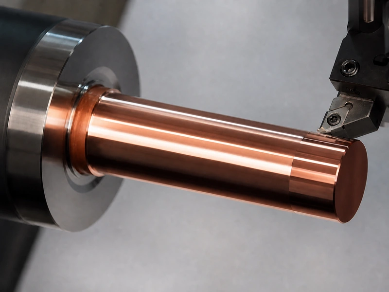
Identifier le matériau avant de choisir l’outillage
« Cuivre » peut désigner le cuivre pur et plusieurs familles d’alliages. Un plan indiquant simplement cuivre ne suffit donc pas pour justifier un transfert de paramètres. Vérifiez la nuance exacte, l’état métallurgique si pertinent et l’exigence de conductivité ou de fonction avant de considérer l’exemple d’un fournisseur comme applicable.
| Identification du matériau | Éléments utilisables de ce guide | Première décision |
|---|---|---|
| Cuivre pur/corroyé courant à haute conductivité confirmé, dont C101/C110 | Le mécanisme BUE, la géométrie de cisaillement net, les indications de refroidissement et le calcul de tournage C110 identifié constituent un point de départ conditionnel. | Conserver matériau, opération, arête, diamètre, engagement et conditions de montage avec l’essai. |
| Autre alliage de cuivre | Les alliages de cuivre peuvent présenter un comportement de copeaux et une usinabilité différents du cuivre pur. | Confirmer l’alliage et l’exigence fonctionnelle avant de reprendre un réglage pour cuivre pur. |
| Cuivre-tungstène | Les sources utilisées ici ne fournissent aucune donnée de géométrie, vitesse, avance, refroidissement, usure ou intégrité de surface pour le cuivre-tungstène. | Arrêter le transfert. Utiliser une gamme spécifique au matériau. |
Le cuivre pur est difficile ici parce qu’il est ductile et adhérent, pas parce qu’il serait particulièrement dur. Le guide DFM de MakerStage décrit le cuivre se soudant sur la face d’outil sous température et pression de coupe, formant une arête rapportée (BUE). Ce dépôt modifie la géométrie effective et peut transformer un cisaillement net en surface rugueuse et arrachée. Rapid Efficient décrit le comportement associé comme étalement, entraînement et collage sur l’arête.
Règle de décision : si le brut n’est pas confirmé comme cuivre pur/corroyé courant, ne commencez pas par copier les indications de PCD, refroidissement, vitesse ou avance. Confirmez d’abord le matériau.
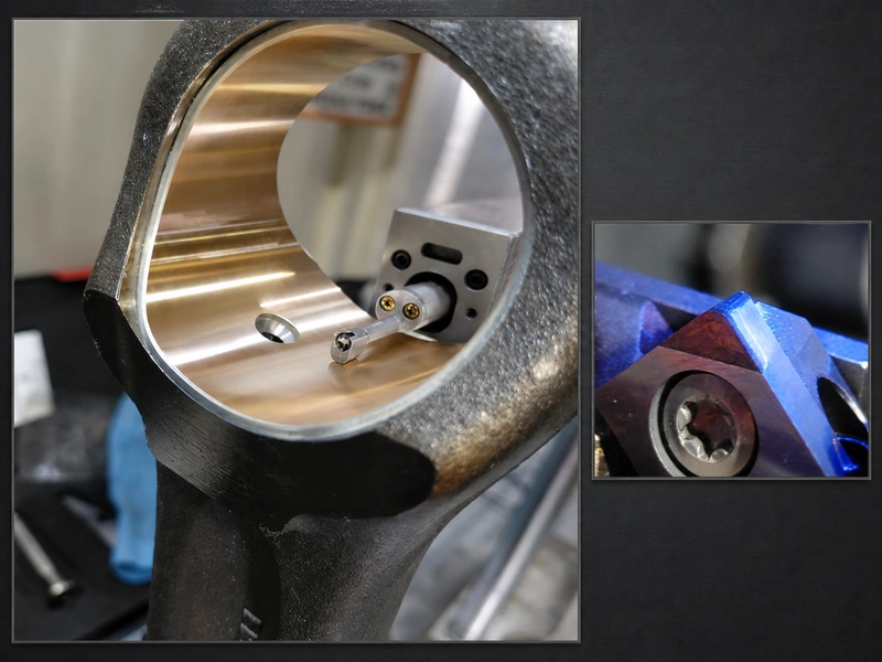
Pour du cuivre pur confirmé, privilégier cisaillement net et sortie des copeaux
Choisir l’outil ne revient pas simplement à prendre l’arête la plus dure. Il faut savoir si elle coupe la matière ductile avant frottement, déformation et adhésion. Pour C101/C110, MakerStage préconise des outils vifs et très polis, un angle de coupe positif de 8–12°, du carbure non revêtu ou du PCD, et un arrosage abondant à haute pression dirigé vers la face de coupe. C’est l’orientation d’un fournisseur pour le cuivre pur, pas un tableau normalisé du secteur.
Cette géométrie a un but pratique. Une arête vive, polie et positive réduit la tendance à pousser le cuivre ductile devant la coupe. Le fluide dirigé vers la face de coupe contribue à maîtriser la zone et à éloigner les copeaux ; ce n’est pas une consigne universelle d’augmentation de pression sur toute machine. Porte-outil, faux-rond, porte-à-faux, opération, engagement et arête réelle peuvent encore changer le résultat.
Le PCD est ici une orientation de matériau de coupe pour les non-ferreux, pas une solution garantie. La présentation du PCD par More Cutting Tools indique une faible affinité du PCD avec les métaux non ferreux et une arête vive, tout en avertissant que diamant/PCD peut se carboniser et défaillir lorsque la température de l’air dépasse 600 °C. Cette limite compte : l’étiquette PCD ne définit pas la bonne préparation d’arête, stratégie de refroidissement, fixation ou fenêtre de procédé pour une pièce donnée.
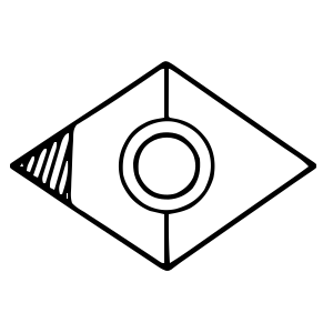
Pour consulter une famille candidate après avoir décidé du procédé, utilisez uniquement comme navigation la rubrique Plaquettes PCD. Le lien ne confirme ni aptitude au cuivre, ni géométrie, disponibilité, compatibilité avec le fluide ou performance d’une plaquette donnée. Il ne s’applique pas au cuivre-tungstène.
Conserver toutes les conditions lors de la conversion de vitesse périphérique en RPM
Vitesse et avance ne sont pas des propriétés indépendantes du cuivre. Avance par dent, largeur de coupe, régime, géométrie, engagement, réponse machine et évacuation peuvent interagir. Une étude de micro-outils PCD sur des réseaux en cuivre a étudié ensemble largeur de coupe, avance par dent et régime pour la précision dimensionnelle et les bavures. Elle invite à traiter l’essai comme un système plutôt qu’à exporter une valeur isolée. L’étude Springer concerne le micro-usinage de réseaux en cuivre, pas un tableau de fraisage de production.
Calculateur de vitesse de tournage en RPM
Saisissez une vitesse de coupe déjà choisie pour le matériau confirmé, l’outil et le montage, puis le diamètre actuel de la pièce. Le calculateur convertit ces données en régime de broche RPM ; il ne choisit pas la vitesse de coupe.
Conversion d’unités uniquement. Confirmez les limites machine et conservez matériau, outil, engagement, refroidissement et montage avec chaque essai.
Symboles : n = régime de broche en rpm ; Din = diamètre actuel de la pièce en pouces ; Dmm = diamètre actuel de la pièce en millimètres ; et Vc = vitesse de coupe validée en m/min.
Les valeurs par défaut reproduisent l’exemple documenté de tournage C110 au carbure : 300 SFM et 1.5 in donnent 764 RPM. L’exemple montre comment unités et données restent associées au résultat ; ce n’est ni un réglage de fraisage ni une recommandation générale pour le cuivre.
La source citée recommande la régulation à vitesse de coupe constante lorsqu’elle est disponible, quand le diamètre change en dressage ou en profilage. Avant d’utiliser un résultat, conservez matériau, opération, diamètre, type d’outil, engagement, refroidissement et conditions de montage.
Diagnostiquer l’état physique avant de modifier plusieurs valeurs
| Symptôme | État physique probable à examiner | Première vérification | Action contrôlée |
|---|---|---|---|
| Matière sur l’arête ; surface irrégulière et arrachée | L’arête rapportée (BUE) peut modifier la géométrie effective. | Examiner l’arête pour détecter la matière adhérente et confirmer son état vif/poli et sa géométrie positive. | Corriger le chargement ou l’état d’arête observé, puis vérifier une modification sur une pièce contrôlée. |
| Bavure repliée ou étalée, surtout en bord ou au débouchage | La matière ductile peut être poussée et frottée plutôt que cisaillée nettement. | Examiner acuité/usure, frottement et conditions locales de débouchage. | Rétablir une arête de finition dont l’acuité est connue ou corriger la géométrie documentée ; revérifier avant de modifier des variables sans rapport. |
| Les longs copeaux marquent la pièce ou gênent la coupe | Les copeaux ductiles peuvent mal se fragmenter et rester dans la zone de coupe. | Vérifier évacuation, type d’opération, engagement et éventuelle recoupe des copeaux. | Améliorer le trajet des copeaux selon la gamme propre à l’opération, puis réexaminer la surface. |
| Mauvaise finition sans BUE évidente | Le défaut peut provenir du bridage, du faux-rond/porte-à-faux, d’une trajectoire instable, de marques de serrage ou de la manutention. | Inspecter la surface avant nettoyage ou manipulation, puis vérifier fixation et stabilité de l’outil/du montage. | Effectuer une correction de montage et comparer la pièce contrôlée suivante avant de modifier une valeur de coupe. |
Cette séquence est volontairement prudente. Elle évite de modifier simultanément vitesse, avance, outil, refroidissement et bridage sans rien apprendre de la pièce suivante. Les sources étayent les mécanismes et risques individuels ; vérifier une seule modification à la fois est la méthode pratique de l’article pour garder le diagnostic interprétable.
La maîtrise des bavures appartient aussi au procédé, pas seulement à la finition manuelle. Datron recommande un autre outil, bien affûté, pour la finition, car les outils vifs réduisent les bavures. C’est une recommandation générale CNC : elle justifie un contrôle d’état d’arête, pas une avance propre au cuivre.
Quand cesser d’utiliser cette page comme aide à la décision
Ce guide n’est utile que si ses conditions restent explicites. Il vise du cuivre pur/corroyé courant confirmé, une démarche de coupe documentée et des défauts vérifiables un à un. Arrêtez-vous et obtenez des preuves spécifiques au matériau si le brut est un autre alliage aux exigences différentes, si l’opération ne correspond plus à l’exemple de tournage documenté, ou si le matériau est du cuivre-tungstène.
Pour usiner le cuivre, le prochain pas fiable est rarement une valeur plus rapide copiée ailleurs. C’est un matériau confirmé, une arête qui cisaille nettement, un trajet de copeaux ouvert, une méthode compatible de refroidissement/manipulation et une vérification contrôlée du symptôme réel.