




Hartdrehen: bedingungsbezogene Ausgangswerte wählen und erproben
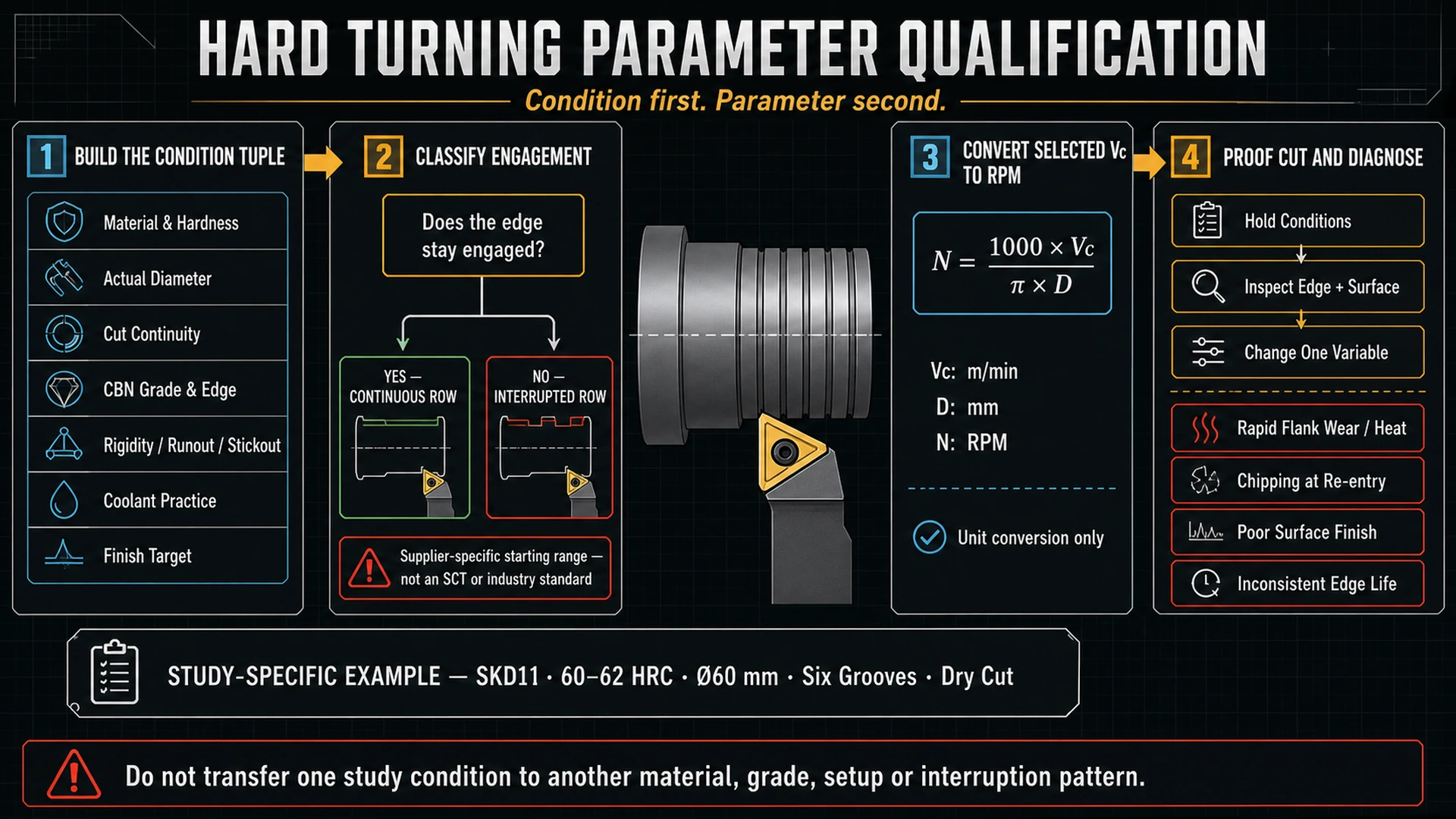
Wählen Sie beim CBN-Hartdrehen die Ausgangszeile danach, ob die Schneide im Eingriff bleibt, und halten Sie Härte, tatsächlichen Werkstückdurchmesser, CBN-Sorte und Schneidenzustand, Steifigkeit und Oberflächenziel mit dieser Zeile fest. Für kontinuierlichen Schnitt gilt nur eine kontinuierliche Quellenzeile. Jeder Kontaktverlust mit Wiedereintritt verlangt die unterbrochene Zeile. Ein vollständig unterbrochenes Teil erfordert eine zusätzliche Prüfung anhand einer vergleichbaren Herstellerempfehlung oder Studie mit passenden Einsatzbedingungen.
Dieser Artikel verwendet drei Arbeitsklassen. Sie sind kein Industriestandard; die verwendeten Quellen definieren keine numerische Schweregrenze:
- Kontinuierlich: Die Schneide bleibt im Kontakt mit dem Werkstück.
- Leicht unterbrochen: Die Schneide verliert an einem örtlichen Merkmal wie einer Riefe den Kontakt und tritt wieder ein. Dies beschreibt das Entscheidungsproblem, keine genormte Klasse.
- Stark unterbrochen: Wiederholter Eingriffsverlust an mehreren Merkmalen. Die unten verwendete Studie mit vollständig unterbrochenem Schnitt ist ein konkretes Beispiel, keine allgemeine Einstellung für diese Klasse.
Schnittkontinuität vor Zahlenwahl einordnen
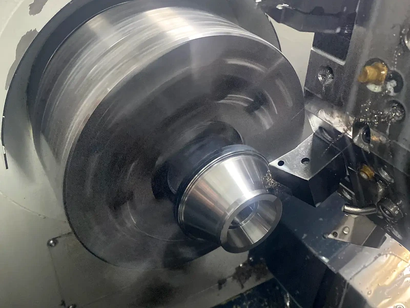
Unterbrochener Schnitt bedeutet Ein- und Austritt der Schneide; beim kontinuierlichen Schnitt bleibt sie im Kontakt. Nuten, Verzahnungen und Zahnräder können diesen Unterschied erzeugen. Halnns Definition stützt die Kontaktunterscheidung, seine kommerziellen Hinweise sind jedoch kein Parameterstandard.
Entscheidend ist nicht, ob das Teil überwiegend rund aussieht. Fragen Sie, ob und wie oft die Schneide wieder in Material eintritt und ob Halter und Spannung dieses Ereignis ohne Bewegung wiederholen können. Ein Forumsfall zu einer verchromten Hydraulikstange mit Riefen zeigt, warum ein lokaler Wiedereintritt nicht als ununterbrochenes Drehen gelten kann, besonders bei nur geschätzter Härte. Es ist ein bedingungsspezifisches Problem, kein Beleg für eine allgemeine Parameterregel. Es dient nur als ergänzender Kontext.
Entscheidungsregel: Tritt die Schneide wieder ins Werkstück ein, beginnen Sie nicht mit einem kontinuierlichen Wert, nur weil der größte Umfangsanteil geschlossen ist. Verwenden Sie die unterbrochene Zeile derselben Lieferantentabelle und prüfen Sie Schneide und Oberfläche vor Änderung einer Größe.
Einsatzbedingungen vor Tabellenwahl erfassen
Notieren Sie Werkstoff und gemessene Härte, tatsächlichen Schnittdurchmesser, Kontinuitätsklasse, CBN-Sorte und Schneidenzustand, Halter- und Spannsteifigkeit, Kühlpraxis und Oberflächenziel. Dies sind keine optionalen Fußnoten. CBN-Sorte, Werkstückhärte, Schnittgeschwindigkeit und Vorschub beeinflussten Kräfte und Rauheit in der zitierten AISI-H13-Studie, die 45, 50 und 55 HRC untersuchte, nicht sämtliche gehärteten Stähle. CBN-Studie zu AISI H13.
Steifigkeit gehört zu den Bedingungen, da wechselnde Oberfläche oder Schneidenversagen von Halter, Spannung, Rundlauf oder Auskraglänge statt vom nominellen Vorschub stammen können. Die Quellen nennen keine Steifigkeitsgrenze. Eine schwache Einrichtung verlangt daher einen vorsichtig erprobten Ausgangspunkt, keinen erfundenen reduzierten Vorschubwert.
Lieferantenspezifische Ausgangszeile wählen
Die folgende Tabelle gibt breite CBN-Ausgangsbereiche für gehärteten Stahl von OnmyToolings wieder. Es sind lieferantenspezifische Daten, keine SCT-Daten, keine ISO/DIN/ANSI-Norm und keine Empfehlung für jede CBN-Sorte, Härte, Halterung oder Maschine. Vc ist die Schnittgeschwindigkeit, ap ist die Schnitttiefe und f ist der Vorschub pro Umdrehung.
| Operation und Eingriff | Vc (m/min) | ap (mm) | f (mm/rev) | Zeile verwenden |
|---|---|---|---|---|
| Schruppen, kontinuierlich | 80-160 | 1.0-2.5 | 0.1-0.5 | Breiter CBN-Ausgangsbereich des Lieferanten für gehärteten Stahl bei kontinuierlichem Schnitt. |
| Schruppen, unterbrochen | 80-125 | 1.0-2.5 | 0.1-0.5 | Breiter unterbrochener Ausgangsbereich des Lieferanten; bei Wiedereintritt der Schneide verwenden. |
| Fertigdrehen, kontinuierlich | 125-210 | 0.1-0.5 | 0.05-0.2 | Breiter Fertigdrehbereich des Lieferanten bei dauerhaftem Schneideneingriff. |
| Fertigdrehen, unterbrochen | 100-150 | 0.1-0.5 | 0.05-0.2 | Breiter unterbrochener Fertigdrehbereich des Lieferanten; nicht ohne Anwendungsprüfung auf eine vollständig unterbrochene Studienbedingung übertragen. |
OnmyToolings verlangt ausdrücklich, die Werte als Ausgangsbereiche zu behandeln, Schneide und Oberfläche zu prüfen und jeweils eine Größe zu optimieren. Die Unterscheidung zwischen kontinuierlichen und unterbrochenen Zeilen hilft bei der ersten Wahl. Sie definiert weder leichte und schwere Unterbrechung noch bestätigt sie eine bestimmte SCT-Platte oder passende Sorte und Schneidenpräparation.
Bei leicht unterbrochener Bearbeitung nehmen Sie zunächst die unterbrochene Lieferantenzeile. Bilden Sie keinen Mittelwert zwischen kontinuierlichen und unterbrochenen Zeilen. Bei starker Unterbrechung prüfen Sie zuerst, ob Werkstoff, Härte, Plattenzustand, Trocken-/Kühlpraxis, Durchmesser und Unterbrechungsmuster einer erprobten oder herstellerseitig gestützten Anwendung ähneln. Wiederholter Wiedereintritt kann aus Gründen scheitern, die ein breiter Bereich nicht zeigt.
Schnittgeschwindigkeit in RPM umrechnen, ohne daraus eine Empfehlung zu machen
Beim metrischen Drehen wird eine gewählte Schnittgeschwindigkeit wie folgt in Spindeldrehzahl umgerechnet:
Dabei gilt:
Symbole: n = Spindeldrehzahl in rpm; Vc = qualifizierte Schnittgeschwindigkeit in m/min; D = tatsächlicher Werkstückdurchmesser in mm; π ist die Kreiszahl.
Dies ist eine Einheitenumrechnung für eine gewählte, bedingungsbezogene Schnittgeschwindigkeit. Sie wählt weder Vc noch Vorschub, Schnitttiefe, CBN-Sorte oder Schneidenpräparation. Bei Durchmesseränderung neu berechnen.
Rechner: Hartdreh-Schnittgeschwindigkeit in RPM
Geben Sie eine bereits für tatsächliche CBN-Sorte, Werkstoff, Härte, Schnittkontinuität und Einrichtung qualifizierte Schnittgeschwindigkeit sowie den aktuellen Werkstückdurchmesser ein. Dieser Rechner wandelt nur Einheiten um; er wählt keine Hartdrehgeschwindigkeit.
Nur Umrechnung. CBN-Sorte, Härte, Kontinuität, Schneidenpräparation, Kühlpraxis und Steifigkeit mit dem Ergebnis festhalten.
Rechenbeispiel: vollständig unterbrochene SKD11-Studienbedingung
Ein IJRES-Versuch zum vollständig unterbrochenen Hartdrehen bearbeitete trocken ein SKD11-Werkstück mit 60 mm Durchmesser, 100 mm Länge, 60-62 HRC und sechs Nuten. Die Platte wurde mit hohem CBN-Anteil (90%) und TiN-Beschichtung angegeben; Versuchsziel war die Freiflächenverschleißbewertung. Die Studie berichtete ein optimiertes Modell bei Vc = 120 m/min, f = 0.167 mm/rev und Schnitttiefe d = 0.139 mm für ihre Studienbedingung; die Validierung ergab 137.1 Mikrometer Freiflächenverschleiß. Die zitierte Studie ist die begrenzte Belegquelle.
Nur mit der angegebenen Schnittgeschwindigkeit und dem Durchmesser:
Runden Sie nur auf die nutzbare Auflösung der Steuerung. 636.6 RPM ist ein abgeleiteter Spindelbefehl für die vollständig unterbrochene SKD11-Studienbedingung: 60-62 HRC, 60 mm, sechs Nuten, trocken, TiN-beschichtete Platte mit hohem CBN-Anteil. Es ist keine Startempfehlung für andere harte Stähle, CBN-Sorten, Unterbrechungsmuster, Durchmesser, Oberflächenziele oder Einrichtungen.
Anpassungsrichtung anhand des Probeschnitts wählen
Prüfen Sie Schneide und Oberfläche nach dem ersten Versuch unter beibehaltenen Bedingungen. Halten Sie Quellenzeile und Einrichtungsprotokoll lange genug konstant, um Änderungen zu erkennen. Ändern Sie dann eine Größe, nicht Geschwindigkeit, Vorschub, Tiefe, Sorte und Einrichtung gleichzeitig.
| Beobachtetes Ergebnis | Erste Prüfung | Begrenzte Anpassungsrichtung | Beleggrenze |
|---|---|---|---|
| Freiflächenverschleiß steigt rasch oder Wärmespuren treten auf | Kontinuitätsklasse, tatsächliche Geschwindigkeit und Ähnlichkeit zur vollständig unterbrochenen trockenen SKD11-Studienbedingung prüfen. | Bei vergleichbarer Anwendung zuerst die Geschwindigkeit prüfen: Im getesteten Versuchsplan der IJRES-Studie hatte sie den stärksten Einfluss auf Freiflächenverschleiß. Eine Größe ändern und erneut prüfen. | Dies beweist nicht, dass geringere Geschwindigkeit jeden Verschleißmechanismus oder Werkstoff korrigiert. |
| Ausbrüche beim Wiedereintritt | Schnitt als unterbrochen neu einordnen; Plattensorte/Schneide, Halter, Spannung und Wiedereintrittsmerkmal vor Vorschubänderung prüfen. | Zuerst die Unstimmigkeit bei Unterbrechung/Einrichtung beheben. Dann die unterbrochene statt kontinuierliche Lieferantenzeile verwenden und eine kontrollierte Änderung erproben. | Die Quellen schreiben nicht für jeden Ausbruch eine Vorschub- oder Tiefenreduktion vor. |
| Schlechte Oberflächengüte | Oberflächenziel, Vorschubeinheit, Kontinuität, Härte, CBN-Sorte, Schneide, Rundlauf und Steifigkeit prüfen. | Fertigdrehzeile nur bei passender Eingriffsklasse verwenden. Nach mechanischen Prüfungen eine Größe ändern. | Die H13-Studie zeigt Rauheitseinflüsse dieser Größen im getesteten Bereich, berechnet aber nicht die Oberfläche für jede Anwendung. |
| Wechselnde Oberfläche oder Standzeit bei nachgiebiger Einrichtung | Halter-/Spannsteifigkeit, Auskraglänge und Rundlauf prüfen, bevor die Tabelle verantwortlich gemacht wird. | Einrichtung stabilisieren oder Versuchsrisiko durch einen verifizierten Anwendungsprozess senken, dann einen Versuch mit einer variablen Größe wiederholen. | Die Quellen liefern weder Steifigkeitsgrenze noch numerische Kompensationsregel. |
Die Studie zum vollständig unterbrochenen Schnitt berichtete aus der diskutierten Literatur auch mechanischen Verschleiß bei niedrigeren und Diffusionsverschleiß bei höheren Geschwindigkeiten. Dies ist ein Mechanismushinweis für vergleichbares Hartdrehen, kein Ersatz für die Bestimmung des tatsächlichen Verschleißbilds oder CBN-Zustands. Ihr eigenes Versuchsfenster umfasste nur 120, 140 und 160 m/min und darf nicht wie eine Katalogkurve darunter oder darüber fortgesetzt werden.
Qualifizierte Einstellung dokumentieren, Werkzeugfamilie getrennt wählen
Speichern Sie Quellenzeile, Einheiten, tatsächlichen Durchmesser, berechnete RPM, Werkstoff und Härte, CBN-Sorte und Schneidenzustand, Kontinuitätsklasse, Kühlpraxis, Steifigkeitshinweise, Oberflächenergebnis, Schneidenzustand und die nach dem Probeschnitt geänderte Einzelgröße. So wird aus einer Tabellenabfrage ein wiederholbares Prozessprotokoll.
Sind diese Anwendungsdaten bekannt, kann das CBN-Drehplattenprogramm zur Navigation möglicher Produktfamilien dienen. Die Seite belegt nicht, dass eine bestimmte SCT-Platte erforderliche Sorte, Schneidenpräparation, Fähigkeit für unterbrochenen Schnitt, Verfügbarkeit oder Leistung besitzt. Bestätigen Sie diese Angaben getrennt.
Zuerst die Eingriffszeile wählen, RPM aus dem tatsächlichen Durchmesser berechnen, Schneide und Oberfläche prüfen, dann eine Größe ändern. So bleibt der nützliche Quellenbereich mit der realen Anwendung verbunden.